Contents:
This instrument produces exposed high currents as a normal part of its function. High current shorts through rings, wrist bands or other conductive apparel can cause serious thermal burns which may result in permanent injury. Operators are advised to remove all conductive apparel, especially from the hands and wrists, prior to any operation or service of this instrument.
Safety Precautions
Since this instrument provides exposed high currents as a necessary part of its operation, it's very important to maintain certain safety precautions whenever using or servicing it. Be certain you've read and understand the warning above. The high currents produced by this instrument may cause the probe ends to abruptly spot weld themselves to metal objects such as rings and cause a very rapid, searing temperature rise to occur in the object. Rings are a special hazard due both to the higher chance that they may become shorted to the probes or the system under test and because, once super heated, they may be difficult or impossible to remove, thus prolonging the time and extent of injury. However, metal wrist bands, bracelets and any other conductive apparel that could possibly come into contact with this instrument's probes or any part of a unit it is testing are also hazardous and should always be removed before any operation is begun.
Always keep in mind that this instrument can behave as if it were a modest capacity arc welder whenever a test is in progress. In addition to the personal injury hazard, inadvertent probe contact may cause damage to components, wiring, metal panels or other conductive parts. This instrument, like any other high current source, should always be treated with special caution.
Be certain to visually verify that a test is not in progress (test button leds off) upon the completion of any test, or anytime before handling the probes.
Whenever setting the "current adjust" control for a new or modified unit under test, always start with the control set to the full counter clockwise position ("Min." position), then turn slowly clockwise until the desired current is reached.
This instrument provides efficient and accurate stress based testing of safety ground systems to insure that they meet certain performance standards of safety certification agencies such as UL, ETL, TUV, CSA, VDE, BABT and others. It utilizes probes with built in remote sensing or, for multi-point testing or the highest precision measurements, auxiliary Kelvin sense probes. In addition to ground impedance measurements, it can provide and accurately monitor the high currents necessary to test ground system endurance as is required for ground guards on etched circuit boards or in power transformers or other components.
Functionally, the instrument provides low voltage AC current adjustable to 60 amps rms at the frequency of the power source (typically 60 Hz). This current and the voltage differential at the probe tips it induces are both measured by means of digital signal processing in true rms and divided to yield impedance. The value of the current is displayed continuously on a bar graph, and may be selected to be displayed on the primary digital readout at the same time. Normally, however, the digital readout is selected to display the impedance of the device under test. While the impedance measurement range is 0 to 100 ohms, the center of interest is usually in the 0 to 100 milliohm area. Basic specified accuracy is ± 1% for both impedance and current.
Model 309 tests may be automatically timed from one second up to one hour. The user settable test time is displayed on a second digital readout between tests. During tests, this readout automatically indicates the time remaining in a test as a count down timer. A timed test may be reset anytime during the test to the full test time if desired. Also, the timer may be disabled to allow indefinite testing.
The model 309 also includes audio alerts for user settable impedance and high and low test current limits. These alerts are muted between tests.
A modular probe system which incorporates built in remote sensing provides a variety of methods to make efficient connections to the unit under test. Any combination of two Model 100 series probes may be used, or custom probes or international power receptacle banks or other fixtures may be constructed using the Model 104 cut end probe and your custom connector or fixture. A common probe combination is the Model 101 medium alligator clip for connection to chassis points and the Model 102 which plugs into a standard IEC type power receptacle, providing an efficient means of attachment to the ground pin of that receptacle. For multiple point testing or the highest precision measurements, Model 109 Kelvin sensing probes may be used in conjunction with any other probes.
Installing New Operating Software
Like personal computers, this instrument depends upon internal Operating Software in order to function. This software, plus calibration data, user settings and preferences are all stored in programmable flash memory. The Operating Software is designed in such a way that it can be very fully updated whenever desired using the standard serial network port by running the "Model 309 Utility" software application on your PC compatible* computer or a Macintosh running a Windows emulator such as Connectix Virtual PC or Insignia Solutions SoftWindows. The "Model 309 Utility" is available free on our web site, and functions with the Model 308 as well. To get the best performance from your instrument, install the latest Operating Software whenever a new version becomes available on our web site at www.Hypatia.com.
The "Model 309 Utility" provides many features, including a functional virtual instrument which allows the user to control most instrument operations from the computer's terminal, settings and preferences management functions, a continuous duty cycle test program with user settable test on and test off times, an Operating Software installation tool, calibration functions, and other features.
The "Model 309 Utility" communicates over the serial port and automatically establishes network protocols. If desired, you can change the serial mode and speed on the Model 308/9 by invoking preferences using the front panel controls. For specifics about connecting the instrument to a Macintosh or PC compatible computer, see the "Networking" section later in this manual.
A connection to a computer is required to perform the calibration procedure or the optional verification procedure for any instrument with any obsolete version of Operating Software, because installation of the current version of the Operating Software is a certification requirement. (Either procedure may be used to certify the instrument, but the calibration procedure is required to fully optimize accuracy performance. Both are closed case procedures - there are no hardware adjustments in these instruments.)
Hypatia will install the latest version of the Operating Software into any instrument which is returned to us for any reason.
* A Macintosh version is planned, but not yet available.
Once the safety precautions are understood and committed to, you may proceed with familiarization with the instrument and its operation.
To begin, check that the "main power" switch is in the off position, and that the "current adjust" control is rotated to its full counter clockwise ("Min.") position. Plug one end of the power cord into the IEC power receptacle on the back of the cabinet and the other end into a power source meeting the specifications printed above the IEC receptacle.
Two probes must be connected to the instrument, whichever combination of Model 100 series or custom probes or fixture interconnects best suits your connection requirements. Each probe has a rectangular power connector and a modular sense connector on the instrument end. Slide the rectangular housings of the power connectors onto one another in a side by side fashion so that they will mate properly with the front panel connectors. It doesn't matter which one is on which side. Push the power connector pair into the front panel connector pair firmly until they are fully seated. Note: The power connector portions of the probes are not fully engaged until the front edge of the rounded coupling dimples touch the lexan front panel. Be certain the connectors are fully seated. Plug each of the modular sense connectors into the modular receptacles on the front panel, using the right modular receptacle for the right probe and the left modular receptacle for the left probe. Don't cross the sense lines - they must plug in directly above their own power connector for the instrument to yield full accuracy. (If the sense lines are crossed the instrument will warn of polarity errors during the initial few seconds of each test.) Be certain that the measurement ends of the probes are left unconnected to each other or to anything else, and that the "current adjust" control is rotated to its full counter clockwise ("Min.") position.
Controls, Readouts and Ranges:
You may now activate the "main power" switch. During a test, the primary digital readout will read impedance or true rms current according to the setting of the meter mode button located to the right. The basic accuracy of either measurement is ± 1% of reading. The maximum current range is 144 amperes, but the instrument should not be operated above 60 amperes or the specified duty cycle limits due to thermal limitations of certain power components. In the impedance mode, the maximum range is 100 ohms, but for higher impedances the test current will be reduced due to a limitation in the maximum available test voltage. See the graph in the specifications. The bar graph indicates true rms test current at all times. A lighted bar graph window indicates a test current between the value labeled for that window up to the value of the next window. Thus, if the 30 amp window were illuminated, the test current would be between 30 and 32.5 amps. However, the top window, labeled > 40 amps, will remain lighted for all currents higher than 40 amps, and the bar graph will display additions to the 40 amp reading beginning again from the bottom. Thus if the > 40 amp and the 5.0 amp windows were both lighted, the test current would be between 45 and 47.5 amps. The maximum range of the bar graph is 77.5 amperes, but again, the instrument should not be operated above 60 amperes.
If the Model 309 test timer is invoked, the smaller digital readout will read the program test time (from one second up to 59 minutes, 59 seconds) between tests. During a test, it will count down from that reading to zero, at which point the test will automatically terminate and the timer will reset to the program test time. The time base utilizes a precise crystal controlled clock, so the test times are also precise.
Model 309 control settings are adjusted using the "adjust select" button and the "adjust" knob, a rotary actuator. To enter the adjust mode, push the "adjust select" button. The test timer button will flash. Rotate the "adjust" knob to change the test time. To save your setting in flash (non-volatile) memory, press the "adjust" knob once. The timer readout will flash twice to acknowledge that the setting has been stored. If you don't push the "adjust" knob, the new setting will not be retained when the instrument is powered down. Push the "adjust select" button once to advance to the next setting, the milliohm alarm threshold. Adjust and save the setting in the same manner as before. Continue through the next two settings, the current alarm high and current alarm low, and then press the "adjust select" button once more to exit the adjust mode. Note: Whenever you save any setting, the state of the timer, alarms and meter mode controls last used is saved in flash memory as well. Thus you may set the mode of these controls to your preferred default (power on) state and retain them by saving any setting while in the adjust mode.
Optionally, you can adjust and save your settings using the Model 309 Utility application. See the Reading Hold Feature paragraph below for details.
The Model 309 also provides settable user preferences, including network mode, readout resolution, dot or bar graph mode, led brightness, and key click on or off. Hold the "adjust select" button down while turning the instrument on in order to enter the preferences mode. Then adjust and save your settings in turn as before. The instrument will exit the preferences mode when all preferences have been reviewed and the "adjust select" button is pressed once more.
Optionally, you can adjust and save most preferences by using the Model 309 Utility application. See the next paragraph for details.
The reading hold feature displays the last reading, the maximum reading, or the minimum reading, for both impedance and test current, displaying on the main readout, for a limited time or indefinitely. You can specify which reading to hold independently for impedance and current, and the hold time. For example, you could have your instrument hold the maximum impedance and the minimum current (these are now used as the initial settings).
You can use the Model 309 Utility to specify and save your settings and most preferences. To change your reading hold settings, you must use the Model 309 Utility - there are no provisions on the physical instrument for this function.
To do so, connect your Model 308 or 309 to one of your computer's serial ports (see the "Networking" section for specifics). Then launch the Model 309 Utility. It should automatically find your instrument. Then click on the "Instrument" menu and select "Settings". Then adjust and save your settings and preferences in the control window that appears.
If both probes are terminated with alligator clips (Model 101 or 105 probes), they may be connected to the accuracy check resistor mounted on the back of the instrument at this time. Otherwise your probes may be connected to a sample product or for example the opposite ends of a power cord, depending upon your probe types. For the Model 309, for the purposes of familiarization, set the test time to about one minute. Check again that the "current adjust" control is in the full counter clockwise ("Min.") position, then push the "test" or "start test" button. The surrounding leds should flash, and the cooling fan should start. If you are connected to the 100 milliohm check resistor, slowly increase the test current by rotating the "current adjust" control clockwise until a 17.5 amp level is reached. Due to the power dissipation limitation of the check resistor, don't exceed a current of 17.5 amps unless for very short periods, and never exceed 35 amps. If you are connected to a different object capable of handling more current, you may increase the current level accordingly. The Model 309 timer readout should now be counting down by seconds. Set the "meter mode" switch to indicate test current on the primary readout, and verify that the reading matches that indicated by the bar graph. Then set the "meter mode" switch to indicate impedance.
If you are connected to the accuracy check resistor, note the digital reading. Total interface or "contact" impedance between the probe connections and the device under test will be roughly 1 milliohm*, so a reading of about 99 to 103 milliohm should be expected (± 1% instrument tolerance ± 1% check resistor tolerance plus ~1 milliohm interface impedance). For a more thorough appraisal, compare your reading to the test data provided in your performance verification certificate. Push the test button to stop the test or, on the Model 309, allow it to time out. You may leave the "current adjust" control set as adjusted if you'd like to repeat this exercise using the same unit under test. Otherwise turn it to its full counter clockwise ("Min.") position and then disconnect the probes from the unit under test. The cooling fan will remain on for two minutes after the end of a test, or whenever the instrument's internal temperature is above 65° C.
* Add another 1 milliohm interface impedance for each power connector terminated probe utilized (e.g. Model 102 or 103).
Actual production testing of ground systems is performed in a similar manner. A typical example would be impedance testing of your product from it's ground terminal to an exposed conductive point on its cabinet. You should choose a chassis connection point which will give the highest impedance reading. On the Model 309, set the test time and alarms as required. If one probe is configured with an IEC power plug type connector (a Model 102 probe), connect it to the IEC power receptacle of the product being tested. Then attach the other probe to your chassis connection point. If it isn't possible to connect or clip to this point, the probe tip will have to be firmly held in contact during tests (observe safety procedures). A typical requirement would call for a test current of 25 amps and allow a ground system impedance of no more than 100 milliohm. Starting from the full counter clockwise ("Min.") position, turn the "current adjust" control slowly clockwise until the desired current is reached on your sample product. Leave the "current adjust" control at that setting. Then stop the test or allow it to time out. You are then ready for repetitive production testing.
To make a production test, verify that a test is not in progress, connect the probes to your product, then start the test. Visually monitor the impedance reading to determine if your product meets certification requirements. (Optionally, readings may be acquired through a network port by using appropriate software.) Also monitor the bar graph to insure that the test current meets requirements. When your test is complete remove the probes from your product. You are then ready to test your next product.
While it shouldn't normally be necessary to adjust the test current when testing identical products, a variance in the impedance of the ground system under test or the line voltage supplying power to the Model 308/9 can cause a variation of the test current. If a significant variance occurs, readjust the test current to the required value and if necessary press the Model 309 "reset timer" button to continue the test.
Design and Development Applications:
This instrument may also be used for precision ground system analysis in design and development environments. In addition to impedance measurements, it can perform endurance tests on ground guards which separate line voltage circuit areas from other areas on circuit boards or in components. Probes configured with alligator clips (Models 101 or 105) connected to the farthest opposite ends of the guard run are usually best for these tests. A typical requirement would call for the guard run to withstand a current of 25 amps or more for at least one minute with no resulting evidence of degradation.
Floating Measurements, Overloads and Internal Temperature Limit:
The test current and measuring circuits are fully floating with respect to ground except as follows, so it is not necessary to be concerned about corruption of measurements by single point grounding of the unit under test. However, most network ports are connected to the Model 308/9's floating reference, not earth ground. So if you network the instrument the measurement circuits are no longer isolated, and you therefore must not ground the unit under test, because doing so may cause high test currents to be injected into the data ground connections of the instrument and computer support systems, possibly causing damage.
The instrument is overload protected by a thermal circuit breaker built into the "main power" switch which monitors both the line and neutral power conductors and disconnects them both in the case of an extended overload on either. If activated, the switch may be reset after a brief time by turning it back on.
The instrument monitors its internal temperature, and it invokes full time fan operation above 65° C, and prevents testing above 100° C. If the 100° C limit is exceeded, an active test will be terminated and a temperature error will be indicated. The fan will remain on. When cooler, the instrument will return to its normal mode, but will not automatically resume a test.
Standard Remote Sensing, Precision Kelvin Sensing and Multi-Point Testing:
All probes incorporate built in sense lines which acquire voltage information from the probe tips, thus eliminating probe cable resistance and its temperature coefficient as a measurement error source. For the most precise measurements, Model 109 Kelvin sensing probes may be used in conjunction with any other probes. These provide a separate connection for the sense lines, thus eliminating even interface or "contact" impedance as an error source. This can be an important advantage when performing precision analytical measurements, particularly when maximum resolution is required for accurate comparisons of multiple measurements.
To use the Kelvin sense probes, leave the smaller modular connectors from the power probes unconnected. Connect the Kelvin sense probes (Model 109) to the modular receptacles instead. Then connect the small Kelvin sense alligator clips to your unit under test, adjacent to but not directly touching the power probe connections. Also, be certain that the right Kelvin sense line is connected to the same side of the load as the right power probe, and similarly for the left sense line and probe. If the sense lines are crossed the instrument will warn of polarity errors during the initial few seconds of each test.
The Model 109 probes can also be useful for certain multi-point testing situations as follows: If readings need to be taken between multiple points on a unit under test, the power probes may be connected to the furthest opposite ends of the area of interest, and then the Model 109's small alligator clips may be attached to various points within that area. The impedance readings will indicate the precise impedance between the points to which the Kelvin connections are made, even though the test current flows beyond these points as well. Thus multiple location readings may be taken without interrupting a test or altering the high current connections. When using this technique, the instrument will warn of polarity errors if you fail to keep the right side Kelvin connection oriented toward the right side power connection and similarly for the left side connections, but only during the initial few seconds of each test (the instrument doesn't prevent you from conducting reverse polarity tests should you so desire). This technique is accurate only when the full test current flows between the Kelvin connection points. If parallel shunt paths route current away from the path between your Kelvin connection points, your impedance reading may be inaccurate, reading lower than the actual impedance. If uncertain, verify your multi-point procedure by testing in the normal manner and comparing readings.
If desired, you may very easily construct your own Model 109 style Kelvin sense probes using common modular telephone type flat cable and connectors as follows: Terminate the four conductor flat cable with a telephone type modular connector on one end (orientation of the cable doesn't matter) and solder all four conductors to a small alligator clip or other connector on the other end. A 1.5 meter length is suggested for each probe, but not required. (While the impedance of the sense system is low, it is not entirely immune to corruption from stray signal reception, including magnetic fields from the high currents in the power probes. It is therefore recommended that the sense lines be of a convenient but not excessive length.)
Configuring or Customizing Your Probes and Fixtures to Maximize Connection Efficiency:
Your instrument was shipped with your selection of two Model 100 series power probes. You may find additional probes useful if your measurement requirements change or you develop a new connection methodology. Besides offering superior accuracy, the remote sensing modular probe system provides considerable versatility, allowing you to maximize connection efficiency and address unique requirements. The Model 104 cut end probe provides a straightforward and economical means to incorporate your own special connectors or fixtures into your connection strategy. For example, this probe could be connected to a bank of international power receptaclesÝ or other special connectors constructed to meet your specific requirements. In this example the ground terminals should be connected together by a heavy bus, and the probe's power lead and both of the sense lines should be connected to the center of the bus so that the distance from the connection point to the farthest opposite ends of the group of receptacles is minimized. (Physically there are two sense lines, but they serve as a single connection electrically. The use of two lines provides redundancy for extra reliability.) The two sense lines should be connected to the same physical point - don't separate the sense lines as this could cause loop currents in the sense circuit which could compromise measurement performance.
Ý The power terminals of an international receptacle bank could be connected to your dielectric withstand test instrument as well, if you provide appropriate safety features and labeling, thus yielding a single connection fixture for performing both ground integrity and dielectric withstand testing.
Timer Readout Corner Dot Activity:
Your instrument incorporates an analog front end featuring precision programmable gain instrumentation amplifiers with broad measurement ranges. The internal microcontroller sends commands to these devices to auto range the amplifiers as needed. The occasional corner dot activity you may notice on the Model 309 timer readout indicates auto ranging activity, with voltage on the left and current on the right (V/I = Ohms). The upper dot indicates an upward range step, and the lower a downward range step. The microcontroller also acquires zero offset values from the more sensitive current amplifiers shortly after booting and at the end of tests, using this information to mathematically eliminate these errors from measurements. All four corner dots are flashed to indicate this activity.
Connecting
to Your Computer:
In most cases establishing a proper network connection to your
computer is a simple matter of connecting a cable from a serial
port on your computer to the serial port on the back of the Model
308 or 309. From the set of network cables and adapters provided
with your instrument, select a cable or cable and adapter combination
as required to physically mate with one of your computer's serial
ports. (Don't use a parallel port - it won't work.) Then connect
the other end of the cable to the Model 308 or 309 serial port
on the back of your instrument.
In the majority of cases, that's all you need to do to establish a proper network connection. You can then launch the Model 309 Utility, and it should find your instrument automatically, enabling you to operate the instrument in virtual mode, run special tests, update the Operating Software, manage settings and preferences, manage calibration, and perform other functions.
However, if you launch the Model 309 Utility but it doesn't find your instrument even though your serial cable is properly connected, check your computer system to see if other applications have allocated all of the serial ports to other uses, leaving none for the Model 309 Utility. Even if the physical serial port is available, some software applications can render the ports unavailable, and this is usually the cause when the Model 309 Utility is unable to find an instrument. To correct this, the other applications will have to be managed in such a way as to cause them to release a serial port. Applications should release their ports when they are shut down, but not all applications are properly designed in this regard - some fail to release their port when they are shut down. If this is the case, your options include a system restart, software updates that correct the flaw (if available), deinstalling the software, or using a different computer.
Swapping
the Network Card:
The network card cover plate is on the back panel, upper left
corner. Remove the three thumbscrews, then pull on the nylon strap
to slide the card out. To install, slide a card in, pushing on
the right side of the cover plate at least in line with the internal
edge card connector, or even further toward the right edge of
the cover plate, to prevent binding as the connector engages.
Then replace the three thumbscrews.
Network
Cabling:
Use cables designed for the type of network card and port you
wish to employ.
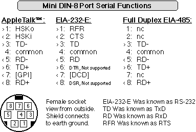
For the Mini DIN-8 multi-mode serial port:
Macintosh connection using AppleTalk or LocalTalk: Use a normal Macintosh hardware handshake printer cable (AppleTalk cable) or a LocalTalk network adapter to connect to the printer or modem port or network on a Macintosh computer (LocalTalk requires software support which is not yet available, and a version 2.2 or higher network card).
PC Connection using EIA-232-E (aka RS-232): Use a Macintosh to modem hardware handshake cable to connect to a PC compatible computer with a DB-25 or DB-25P port connection, or a special Macintosh to DB-9 PC serial cable. Depending upon your cable and computer, you may need a DB-25 or DB-9 gender changing adapter.
These are common cables and adapters (except the Macintosh to DB-9 cable, which is somewhat less common) available from many computer accessory vendors or from Hypatia.
Recent network cards provide jumpers which can be easily repositioned to establish compatibility with either a straight through or mirrored type cable. This provides a "null modem" emulation option, and it eliminates the need for a separate null modem adapter. The jumper settings are illustrated on the network card itself - you can see them by pulling the network card out. If you're not certain which mode you need, simply try both, and use the mode that works.
Model
309 Utility Software Application:
The Model
309 Utility is a PC based application which provides a functional
virtual instrument which allows the user to control most instrument
operations from the computer's terminal, settings and preferences
management functions, a continuous duty cycle test program with
user settable test on and test off times, an Operating Software
installation tool, calibration functions, and other features.
It's available free from our web site. The application communicates
over the serial port and automatically establishes communication
protocols. For more information about this utility see the "Installing New Operating Software"
section above.
Basic
Serial Communication:
You can send text commands to and receive responses from the instrument
over a serial port using common modem applications or specialized
software. Set protocols to N 8 1, and 57.6 kbaud or 9.6 kbaud.
Set the desired serial mode and speed on the Model 308/9 by invoking
preferences using the front panel
controls.
Current network mnemonics are configured as a reduced SCPI
set (Standard Commands for Programmable Instruments). However,
a significant redesign of these mnemonics will occur soon as we
develop instrument modules for compatibility with major virtual
instrumentation software vendors. This doesn't affect the core
Operating Software, internal algorithms or the front panel interface
of your instrument - it's only related to network communications.
Install the latest Operating Software
as new versions become available in order to take advantage of
the latest networking software. Please contact
us for SCPI command set documentation.
> Indicates signal transmitted by the Model 309 (signal
out), < indicates signal received by the Model 309 (signal
in).
- Following function indicates true low
Items in square brackets may not be supported by Hypatia software.
Straight verses mirrored (null modem emulation) connection selectable
with square pin jumpers on version 2.1 and later cards.
Version 2.2 and later cards provide a DTR to DSR hardware handshake
square pin jumper.
The common connection is breakable (link cut and square pin jumper)
to partially isolate common.
Normal Mini DIN-8 to DB-25P (Macintosh to modem) hardware handshake cables are constructed so as to provide a conversion of AppleTalk to EIA-232-E by connecting RD+ to common, opening TD+, and connecting HSKo to both RFR and DTR (RFR and DTR thus shorted to each other). In some cases GPI is opened too, but normally it's connected to DCD, which we think preferable (though it's not presently required). This type cable should be used to establish an EIA-232-E serial connection from the Model 308/9 to a computer with a DB-25 connector. Most systems don't utilize DTR and DSR signaling, and the Model 308/9 does not support these lines in the usual EIA-232-E mode. However, version 2.2 and later network cards provide a hardware echo square pin jumper for those rare cases where required (jumper diagrams are on the card).
Version 2.1 network cards require a modification to the SP333 IC as follows: Pin 1 patched to pad 28, pin 28 patched to pad 1. Hypatia will perform this modification on all cards which are returned for any other service automatically and without charge.
Hypatia products are warranted to the original purchaser to be free from defects in material and workmanship under normal use and conditions for a period of two years from the date of original delivery. Hypatia Inc. will replace or at its discretion repair and return defective units within three weeks with no charge except a $10.00 shipping and handling fee per unit upon their prepaid shipment to Hypatia within the warranty period.
This warranty is void if the unit in question has been visibly damaged by accident or misuse, if the unit has been serviced or modified by anyone other than an authorized representative of Hypatia, or if any warranty seal has been broken.
This is the only warranty expressed or implied given by Hypatia. Any warranty implied under State Law shall be limited to two years from original delivery to the original purchaser. Specifically excluded from this warranty is damage resulting from acts of any deity, malicious mischief, vandalism, riots, wars, improper installation or neglect in the operation or maintenance of the unit or misunderstanding of the properties of the unit. Under no circumstances shall Hypatia be obligated for consequential or other damages of any kind or description, losses or expenses in connection with or by reason of the use of, or inability to use the unit for any reason.
This warranty provides you with specific legal rights, and you may have additional rights which vary from state to state. For example, some states do not allow exclusion of consequential damage.
Any service required for any reason after the warranty period will be performed by Hypatia upon the purchaser's request according to normal Hypatia service charges in affect at the time.
Text contents V1.30, 20 March 2001
© 1995 -2001 Hypatia Inc.
Notes and Late News as of 17 January 2008
Upgrade to the Latest Accuracy and Resolution Refinements (Free in Many Cases):
The latest generation of hardware utilizes 16 bit A/D conversion, rather than the previous 10 bit A/D conversion, on both the current and voltage channels, yielding significantly improved overall accuracy and resolution. For those owners of 10 bit based hardware, board swaps can be made to upgrade your instrument to the latest hardware. This upgrade, including certified calibration, is free for early customers, but costs $300 for others. Check your serial number to see which category your instrument falls into. While the performance of every generation of Model 308/9 hardware is higher than is required in most environments, the enhanced accuracy and resolution of the latest design combined with software utilities now under development will provide certain important advantages in many manufacturing environments. Please contact Hypatia if you are interested in this upgrade.
Network Cards and Cables:
Development of software for the IEEE-488 network card has been placed on hold due to lack of interest in this legacy protocol, even though the current version 2.2 network card supports IEEE-488 hardware when fully loaded. Resources will instead be directed to Universal Serial Bus (USB) and, later, IEEE-1394 and other modern networking technologies. In most cases the current version 2.2 multi-mode serial network card, which provides AppleTalk, LocalTalk, EIA-232-E, EIA-422, and EIA-485 (LocalTalk, EIA-422 and EIA-485 require software support which is not yet available), is more than adequate to meet automation requirements.
We've not yet incorporated the serial cables and adapters descriptions in our accessories literature, but we have shipped one complete set per instrument to every instrument owner without charge. Additional sets may be ordered at a very modest cost. These are common Macintosh type hardware handshake printer or modem cables and gender changers (the modem cables connect to a PC type port, often requiring the gender changer), so there's a chance you already have what you need or have quick access to it.
ETL Listing:
The Models 308 and 309 were listed to UL3111 by ETL until 1 January 2008. In addition, we accomplished the listing at an enhanced current rating of 60 Amps rather than 50 Amps (same duty cycle limits). However, early instruments incorporate a lower rated power switch / circuit breaker (2.5 Amp rather than 3.0 Amp) and list 50 Amp limits on front panel duty cycle nomenclature and 2.5 Amps on the rear panel line power information block. So while early instruments are otherwise fully capable of providing 60 Amp tests, with the lower rated circuit breaker nuisance tripping might be experienced. If you find nuisance tripping to be an annoyance, request a circuit breaker update whenever your instrument is returned for any other service and we'll do so at our component cost ($11.21). While the front and rear panel nomenclature can't be updated, an addendum sticker could be provided.
However, as of 1 January 2008 this instrument is no longer listed to UL 3111 by ETL. The design, construction, testing, and calibration of the instrument has not changed, but rather Hypatia no longer maintains the certification service of ETL due to the high costs of the service relative to the sales volume of this instrument. Please contact Hypatia Inc.if you have questions or concerns about this aspect of the instrument.
© 1995 -2008 Hypatia Inc.
Hypatia Inc. Contact Information ucecage@Hypatia.com. Report mail misconduct to uce@ftc.gov.